4. OBS File
The .obs file contains simple observations and parametric stations declarations.
Each line in an .obs file defines:
a simple observation (see Simple Observations)
a parametric station (see Parametric Observations)
a reference to an .obs subfile (see Subfiles)
4.1. Simple Observations
As mentioned in Overview, all values and sigmas are in meters for linear observations and in grads (gons) for angular observations.
4.1.1. Protocol for Simple Observations
Simple observations definition contains the following fields:
\(code\ origin\ target\ value\ \sigma_{abs}\ [\sigma_{rel}\ [h_{station}\ h_{target}]]\ [*comment]\)
code: observation code (if negative, the observation will be deactivated as explained in Deactivated Observations)
- for linear observations:
1or3: slope distance adjusted for atmospheric propagation2: geodetic distance at ellipsoid level between two points4: height difference between two points9: planimetric centering14: Easting coordinate difference15: Northing coordinate difference
- for angular observations:
5: horizontal angle6: zenith angle without refraction correction7: reference of horizontal angles’ round8: azimuth between two points
origin: station name
target: target name
value: observation value
\(\sigma_{abs}\): fixed part of observation’s standard deviation (if negative, the correspondant observation will be deactived as explained in Deactivated Observations)
\(\sigma_{rel}\): standard deviation relative to computed distance between the two points’ coordinates at current iteration
\(h_{station}\): station height
\(h_{target}\): target height
Note
The planimetric centering (code 9) is a pseudo-observation and it is replaced, when importing the .obs file, by two observations: one observation with code 14 and one code 15 and measured value is not taken into account, it is forced to 0.
Note
A reference of horizontal angles’ round (code 7) adds a new unknown in orientation; all the measurements code 5 from the same station following this code will be in the same round. If a code 5 is not preceeded by a code 7, it will be considered as a reference of horizontal angles’ round.
Note
The final precision of an observation takes into account the absolute precison and the one relative to the computed distance between the two points’ coordinates at current iteration:
for linear measurements: \(\sigma_{abs} + \sigma_{rel} \cdot distance\)
for angular measurements: \(\sigma_{abs} + \frac{\sigma_{rel}}{distance}\)
Note
In case of required high precision, it is not recommended to use the heights of the station and target, as they have no precision. It is necessary to duplicate the points at each height difference and use a planimetric centering (code 9) and height difference between the two points (code 4), for which a precision can be defined (see Example of Simple Observations File).
4.1.2. Example of Simple Observations File
*code origin target value  sigma_abs sigma_rel h_station h_target

 8    S1     S5    300.0000 .0002    0.00      .0000     .000

 *Station 1
 7    S1     S3       .0000 .0020    0.001                      *no heights
 5    S1     S2    391.3030 .0020    0.001     .0000      .0000 *angle_precision=2mgr+1mm/Dcoord
 6    S1     S3     99.9280 .0020    0.00     1.6170     1.5630
 6    S1     S2     99.8060 .0020    0.00     1.6170     1.5790
 1    S1     S2     10.1060 .0010                               *no sigma_rel, no heights
 1    S1     S3     12.1360 .0010    0.0001                *dist_precision = 1mm + 0.0001*Dcoord

 *Station 2
 7    S2     S1       .0000 .0020    0.001     .0000     .0000
 5    S2     S3    220.3200 .0020    0.001     .0000     .0000
 6    S2     S1    100.4150 .0020    0.00     1.5560    1.5560
 6    S2     S3     99.5980 .0020    0.00     1.5560    1.5950
 3    S2     S3     13.6450 .0010    0.000    0.0000    0.0000

*Centering of station S5 above groundmark M5
 9    M5    S5       0.000  0.003    0.0001 *horizontal_precision: 3mm on E, 0.1mm on N
 4    M5    S5       1.619  0.005    0.0001 *dist_precision=5mm + 0.1mm*Dcoord
4.1.3. Deactivated Observations
A simple observation can be deactivated in order to be removed from the bundle adjustment computation while being kept in the final report (grayed out) and computing its residual.
Observations can be temporarily deactivated in the graphical user interface (see Changing Observation Status) for quick tests.
In order to record the status of observations, all changes must be done in the .obs files. To deactivate an observation in the .obs file, add a - in front of its code or its absolute precision.
Example:
 7 S1  S3     .0000    .0020  0.001  .0000  .0000  * active
 6 S1  S3   99.9280   -.0020  0.00  1.6170 1.5630  * deactivated
-5 S1  S2  391.3030    .0020  0.001  .0000  .0000  * deactivated
 5 S1  S2  391.3030    .0020  0.000  .0000  .0000  * active
*5 S2  S3  220.3200    .0020  0.001  .0000  .0000  * commented, hence removed
4.2. Parametric Observations
A parametric observation uses a subfile containing a list of observations sharing a set of unknowns.
They are declared in an .obs file and each parametric observation type has its own protocol.
4.2.1. Cartesian Subframes
The protocol of a cartesian subframe (code 11) in .obs file is:
\(11\ origin\ @file.xyz\ [vertical\ [K]]\ [*comment]\)
Code 11 is used in case of frame change computation or terrestrial lidar measurements adjustment.
Optional parameters:
vertical:
V(or1) indicates that the station is verticalized, i.e. the subframe’s Z axis is vertical.N(or-1) means that the station isn’t verticalized (default: not verticalized)K: factor to be applied to the standard deviations in the cartesian subframe file (default: 1)
The observations file .xyz contains the cartesian coordinates of points in a subframe centered on origin. Each line in the .xyz file contains the point name, its coordinates in the subframe and its precision(s). Therefore, the possible protocols in .xyz file are:
\(target\ X\ Y\ Z\ \sigma_{XYZabs}\ [*comment]\)
\(target\ X\ Y\ Z\ \sigma_{XYZabs}\ \sigma_{XYZrel}\ [*comment]\)
\(target\ X\ Y\ Z\ \sigma_{Xabs}\ \sigma_{Yabs}\ \sigma_{Zabs}\ \sigma_{XYZrel}\ [*comment]\)
\(target\ X\ Y\ Z\ \sigma_{Xabs}\ \sigma_{Yabs}\ \sigma_{Zabs}\ \sigma_{XYZrel}\ h_{target}\ [*comment]\)
The target height (\(h_{target}\)) is given along the vertical.
Example of code 11 .xyz file:
101   2.373710    7.663746  -1.996344 0.002
102 -14.941542   12.140255  -2.473924 0.003 0.00002
103 -20.106478   -0.393074  -0.579412 0.002
104 -16.827297  -16.081907   1.832123 0.005
105  -2.921242  -18.014613   2.047338 0.002
A negative \(\sigma_{abs}\) on a dimension will deactivate the corresponding observation(s).
Note
In the .xyz file, a 0 0 0 measurement is not allowed, as this describes the origin of the subframe, that is given in the .obs file.
Note
In the .xyz file, all coordinates must be cartesian coordinates. In order to build a .xyz file from Comp3D outputs, it is mandatory to use cartesian coordiantes and not a .cor/.new file (see Export Coordinates).
A subframe has three orientation parameters unless it is verticalized, in which case it has only one orientation parameter.
4.2.2. Polar Subframes
The protocol of a polar subframe (code 12) is:
\(12\ origin\ @file.xyz\ [vertical\ [K]]\ [*comment]\)
Code 12 is used in case of non-verticalized total station, laser tracker or photogrammetric measurements.
Optional parameters:
vertical:
V(or1) indicates that the station is verticalized, i.e. the subframe’s Z axis is vertical.N(or-1) means that the station isn’t verticalized (default: not verticalized)K: factor to be applied to the standard deviations in the polar subframe file (default: 1)
The observations file .xyz contains the polar coordinates of points in a subframe centered on origin. Each line in the .xyz file contains the point name, its polar coordinates (pseudo-horizontal angle \(\alpha\), pseudo-vertical angle \(\beta\), distance) and their precisions.
Polar measurements in instrument subframe are as follows:
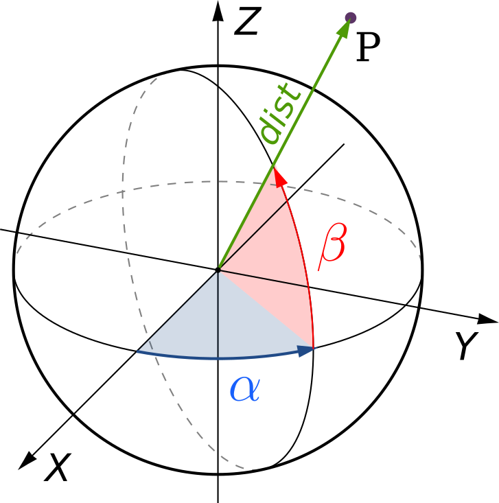
The possible protocols in .xyz file are:
\(target\ \alpha\ \beta\ dist\ \sigma_{\alpha\beta_{abs}}\ \sigma_{dist_{abs}}\ \sigma_{dist_{rel}}\ [*comment]\)
\(target\ \alpha\ \beta\ dist\ \sigma_{\alpha\beta_{abs}}\ \sigma_{\alpha\beta_{rel}}\ \sigma_{dist_{abs}}\ \sigma_{dist_{rel}}\ [h_{target}]\ [*comment]\)
The target height (\(h_{target}\)) is given along the vertical.
Example of code 12 .xyz file:
106  235.1192   1.0954  10.3290  0.0008  0.0004 0.0001
103  314.7766   2.1551  11.9265  0.0008  0.0001 0.0004 0.0001
102  355.5203  15.0235  10.6610  0.0008  0.0001 0.0004 0.0001 0.020
101    5.1767   1.8137   5.7810  0.0008  0.0004 0.0001
A negative \(\sigma_{abs}\) will deactivate the corresponding observation(s).
A a polar subframe has three orientation parameters, unless it is verticalized, in which case it has only one orientation parameter.
When a polar subframe is used for photogrammetric measurements, the distances have to be set to value 0 and have a negative sigma to be deactivated.
Note
To generate .xyz file with MicMac (https://github.com/micmacIGN/micmac) from a 2d points xml file and a camera calibration:
mm3d Bundles2Comp camera_calibration.xml 2d_measurements.xml Distance=0
4.2.3. Rotation Axes
The protocol of a rotation axis (code 18) is:
\(18\ origin\ @file.axe\ [*comment]\)
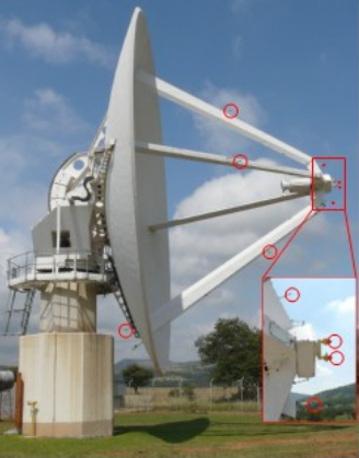
Code 18 is used to determine a rotation axis of an object (e.g. a telescope). Targets are fixed to the structure of the object, topometric measurements on these targets are carried out for different positions of the object when it is revolving around its axis.
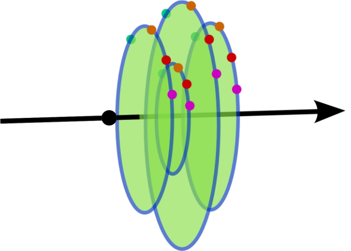
Each target describes a circle when the object moves. Each of these circles is perpendicular to this axis and has its center on the rotation axis.
The origin point is on the axis. Two parameters are added for the axis direction, and two parameters per target: the circle position along the axis and its radius.
The .axe file contains the list of topometric points (\(pt\)) corresponding to the different targets (\(target\)) in the different object positions (\(pos\)) and precisions corresponding to the stability of the circles: stability of radius (\(\sigma_{radius}\)) and stability of their perpendicularity to the axis (\(\sigma_{perp}\)). Therefore, the protocol in .axe file is:
\(target\ pos\ pt\ \sigma_{radius}\ \sigma_{perp}\ [*comment]\)
Example of object axis observation:
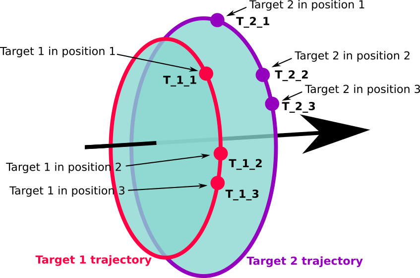
The corresponding .axe file:
*target pos    pt    sigma_radius  sigma_perp
    1    1    T_1_1     0.0005        0.0005
    2    1    T_2_1     0.0005        0.0005
    1    2    T_1_2     0.0005        0.0005
    2    2    T_2_2     0.0005        0.0005
    1    3    T_1_3     0.0005        0.0005
    2    3    T_2_3     0.0005        0.0005
    L  OTHER_POINT
In this example, T_1_1, T_1_2 and T_1_3 represent topometric points and they correspond to the same target (1) fixed on the object, which was turned in three positions (1, 2, 3).
The last line in the example gives a constraint on the position of the origin point along the axis: it will be the orthogonal (hence the L) projection of another topometric point on the axis.
Two axis can be declared on the same origin point: the two axes will intersect at the origin. In this case, there is no need for a L line in the .axe files.
A negative \(\sigma\) will deactivate the corresponding observation.
4.2.4. GNSS Baselines
GNSS baselines (code 19) are vectors between a station and its targets, in cartesian geocentric coordinates frame, with covariances.
Note
GNSS baselines can only be used in a georeferenced project.
The protocol of GNSS baselines .obs file is:
\(19\ pt\ @file.bas\ [K\ [h_{station}]]\ [*comment]\)
pt: starting point of all baselines described in .bas file
optional parameters:
K: factor to be applied squarred to the baselines’ variance-covariance matrix; this amends for potential overestimation of the output precision given by the GNSS software (default: 1)
\(h_{station}\): station height (default: 0)
The .bas file contains, for each point, its name, vector from the station, variance-covariance upper-half matrix, and, eventually, target height. Therefore, the protocol in .bas file is:
\(target\ \Delta X\ \Delta Y\ \Delta Z\ \sigma_{XX}\ \sigma_{XY}\ \sigma_{XZ}\ \sigma_{YY}\ \sigma_{YZ}\ \sigma_{ZZ}\ [h_{target}]\ [*comment]\)
Note
The vector and the upper-half matrix must be given in cartesian geocentric frame. Station’s and target’s heights (\(h_{station}\) and \(h_{target}\)) are given along the vertical.
This file protocol has the advantage of being easily extracted from a sinex file.
The tool Infinity ASC to BAS converts Leica Infinity software .asc files into .bas files.
Note
If the GNSS software has already taken into account all antenna heights, their values should be put to 0 in Comp3D and thus avoid to be taken into account twice.
If Comp3D takes antenna heights into account, instead of the GNSS software, it guarantees that the vertical deflection is used.
To deactivate a baseline, \(\sigma_{XX}\), \(\sigma_{YY}\) or \(\sigma_{ZZ}\) must be set to a negative value. It is impossible to deactivate only one component of a baseline.
Note
\(\sigma_{XY}\), \(\sigma_{XZ}\) and \(\sigma_{YZ}\) might have negative values.
4.2.5. Equality Constraints
Equality contraints are used for points sharing a commun constraint per pair (e.g., same distance).
The protocol to create an equality constraints set in .obs file is:
\(code\ @file.eq\ [*comment]\)
- Available codes:
21: equal height differences22: equal distances
The input file .eq contains the list of points pairs sharing the same constraint:
\(point1\ point2\ \sigma\ [*comment]\)
Example of code 22 .eq file, where the Bn points are on a sphere centered on A:
A B1 0.001
A B2 0.001
A B3 0.001
A negative \(\sigma\) will deactivate the corresponding observation.